If you have ever kicked off a CAD-to-render project that looked straightforward on day one and turned into a rework storm by day five, the problem was not rendering.
It was input risk you did not classify early.
Evaluation exists to move risk detection to the front - while decisions are still cheap.
Why STEP evaluation exists
A STEP export is not a guarantee of "render-ready." Export settings, suppressed subassemblies, and CAD authoring quirks can drop parts, merge bodies, and create topology defects that only show up once you start assigning materials and pushing close-ups.
The STEP file gaps that most often trigger rework
When people say "the STEP is broken," they usually mean one of four categories.
Configurable systems often ship with terminals, columns, mounting kits, and region-specific interfaces. A STEP export may omit a module because the wrong configuration was active, a subassembly was suppressed, or export settings collapsed something unexpectedly.
If the missing module is visible in hero views, this is not cleanup. It is rebuild or re-export.
Fasteners, rubber feet, caps, clips, gaskets, and brackets are often missing or simplified. Engineering may not model them fully, or they live in downstream manufacturing documentation.
In photoreal visuals, these details are credibility anchors. Missing them triggers late-stage churn.
Fillets define product language. STEP geometry can carry over-simplified blends, inconsistent radii, lost sharpness, or broken tangency in visible housings.
Stakeholders feel this before they can name it. Fixes tend to be localized rebuilds using drawings or reference photos.
Non-manifold geometry becomes shading artifacts, broken booleans, and material failures. Typical examples: open shells, self-intersections, zero-thickness faces, flipped normals, and overlapping surfaces after export.
If these issues appear in core housings, you are not repairing. You are reconstructing.
The uncomfortable truth: marketing cannot verify CAD correctness
Marketing owns the launch timeline, but marketing does not own the source of truth for the product definition. A marketing team can verify views, branding consistency, and deliverable format. Marketing cannot reliably verify connector revisions, port counts, accessory inclusion by SKU, or whether a fillet radius matches the released hardware.
When the STEP is incomplete or ambiguous, the stable resolution path is technical drawings, reference images, and engineering confirmation. That is why rebuild from drawings is a normal reality in production CAD-to-render work.
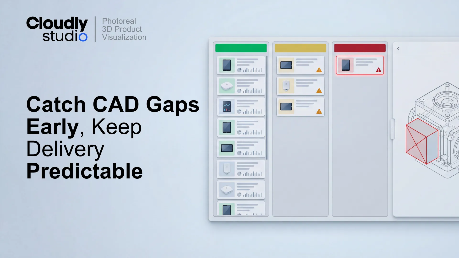
The Green–Yellow–Red model (evaluation decisions you can defend)
The goal is a decision that is easy to communicate and easy to act on. No ambiguity - a clear classification anyone in the project can understand.
Rebuild from technical drawings is normal (and should be planned)
Rebuild is the right call when the STEP is missing visible parts, topology cannot be repaired without distortion, or manufacturing simplifications read poorly in marketing close-ups.
What makes rebuild predictable is having the right inputs:
- 2D technical drawings with key dimensions.
- Reference photos of physical units or prototypes.
- Label files and finish notes.
- A locked view list so you know what actually needs to look correct.
Mini case example: one evaluation call that protected the schedule
The evaluation worksheet: what it should cover
A good worksheet makes the decision repeatable and gives non-CAD stakeholders a language for escalation that is not "the file is bad."
- STEP source, export date, configuration notes
- Assembly completeness (major modules present or missing)
- Small parts completeness (visible details present or missing)
- Fillet and edge fidelity (pass, mixed, fail)
- Topology health (pass, repairable, blocked)
- Reference coverage (drawings, photos, finish notes)
- Decision (Green, Yellow, Red) + one-paragraph note
- Required next inputs + assumptions list
- Timeline impact (low, medium, high)
How to evaluate a STEP file in 20 minutes
Where evaluation fits in a batch workflow
Evaluation is most valuable when you run it at the batch level, not SKU by SKU in isolation: